Solving The Background Problem In The Mid-Infrared
Patrick Hendra
Several times throughout my career we have needed to make measurements in the 1600-1700cm-1 area of the infrared or more rarely near 3000 cm-1 and have had serious problems with atmospheric absorption. In all cases we were using FT instruments flushed with dried air. The normally accepted practice is to run the background, introduce the sample into the chamber as quickly as possible and then wait 15 or 20 minutes before running a spectrum. It was assumed that during this period the wet air would be swept away but we found that the atmosphere in at least part of the instrument invariably contained a slightly different amount of water vapour than it did when the background was recorded. Further, try as we might, the instrument gradually became more contaminated as the day progressed and the situation less and less satisfactory.
Let me tell you about one example of the work we were doing and you will see the problem. When films of polyethylene are strained, in common with all semi-crystalline polymers, massive irreversible stretching occurs to produce a highly oriented sample with unique enhancements of their strength and stiffness. There is a major research interest in working out what happens to the polymer molecules as the unoriented material is deformed to an oriented one. Our approach was to deform and compare the i.r. spectrum as deformation was increased. We were searching for C=O groups which we reasoned would be produced when chains break under stress and the free radical ends oxidise. The number of broken chains are expected to be very small, hence the concentration of C=O groups must be minute. We wanted to detect these groups and to do so quantitatively. The water vapour problem made the work impossible.
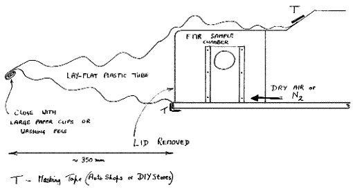
To overcome the difficulty we first tried an air-trap approach. We bought some ‘lay flat’ tube of polythene film from our local DIY store. The ‘lay flat’ material was about 300mm wide. The sample area lid was removed and replaced by a simple metal sheet with a hole in it. The ‘lay flat’ film was opened and taped around the hole and the sample then introduced through the tube. Once introduced, the end was rolled and clipped with a wide paper clip. The setup is shown below:

Figure 1
The arrangement is widely used and it works, but only in a limited sense. Every time a sample is introduced, a small amount of wet air inevitably gets in and therefore the background steadily deteriorates throughout the day. The deterioration is small and usually acceptable but the change in background is unacceptable if high sensitivity work is intended. Ratioing the background against the spectrum inevitably shows up water vapour bands and hence destroyed our results. We needed a system enabling us to change samples without the ingress of ANY air into the machine. An alternative is a method of coping with a background even though it is changing. Let me tell you about methods of tackling both.
Lay flat tubing is available from lab suppliers. Used with a strip welder, it is almost universally used in packaging.
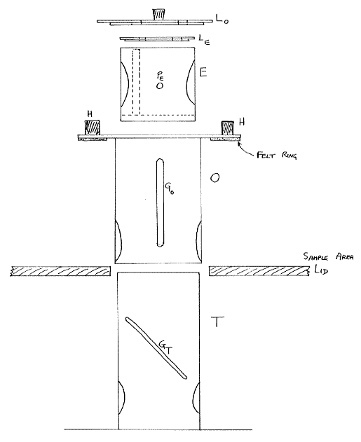
About ten years ago we developed a contraption at Southampton to allow us to introduce the sample and avoid contamination. The device, in effect, was a small elevator inside which was mounted a set of 2×3 inch ‘industry standard’ sample holding rails. The elevator fitted inside two concentric thin tubes, the inner of which was rigidly fixed and screwed to the sample area base. The outer tube came up through a lid and could be rotated. The device is illustrated below:

Figure 2: Sample Changer – Exploded View
Tube T is screwed to the instrument base. O drops over T and seals to the sample area lid. E fits inside O. Pin PE runs in grooves GO and GT hence rotating O moves E rotationally and vertically. Lid LE fits E and LO seals O. Both have holes in them.
Winding the outer tube O moves the elevator E up and down and twists it at the same time. Hence, the holes cut through the tubes and the elevator to allow passage of the infrared beam can be allowed or obstructed.


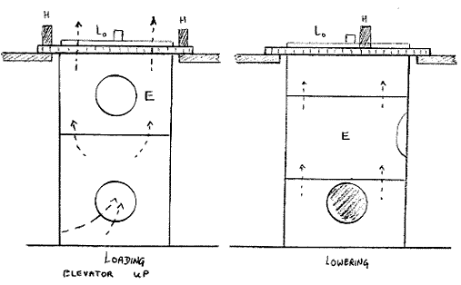
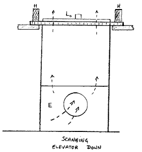
Figure 3
Operation is as follows:
- The tube O is wound round using handles H until the sample elevator is in the up position. The lids are removed and the sample introduced.
- The lids are replaced and the outer tube gently rotated. The elevator descends and rotates until, when it reaches the bottom, the i.r. beam can pass completely through the device, including the sample.
- The spectrum is recorded and when complete the tube is rotated to raise the elevator. Once at the top of its travel, the background is recorded, and finally the lids removed and the sample replaced.
Thus – no delay is involved – the sample can be introduced and removed repeatedly and quickly. How does it work?
One of my postgrads at the time in question was Jackie Ackavan. She claimed the device worked well enough that the background did not effectively change throughout a whole day of continuous use. To be honest (and supervisors have been known to be such) the favourable outcome may well have been influenced by the fact that the FTIR used an air bearing (an ancient Nicolet MX-1) hence the flow of dry air was copious. If a relatively slow purge is used, contamination might have occurred after many sample changes. Anyway – several of these devices were built and used by users of several different Nicolet instruments. Perhaps the sample changer needs re-invention!
An alternative approach is to return to the old double beam technique – or rather the “ratio recording” rather than the “null balance” variants thereof.
Some years ago, one of the commercial FTIRs was provided with a “shuttle”. I am not sure whether it was a great commercial success but the idea was simple. After each scan of the interferometer, a solenoid operated and switched the “sample” for a “reference”. Let us say the “reference” was nothing – just air – then the reference interferogram is that of the background. The “sample” interferogram (which must always be of lower intensity) is that of the background attenuated by the sample. The software puts each into a memory scan after scan, Fourier Transforms, ratios and comes up with a SAMPLE SPECTRUM.
Now, this is exactly what we always do in our infrareds, the difference being that if the background is VARYING, the system allows for it. The old monochromator machines did this as a matter of routine, but the FTs can do the same if called upon.
I have no idea whether all or only some of the manufacturers offered this facility, but Perkin-Elmer did on the 1700 series of instruments. Try asking your manufacturer what they can do. If the answer is “Nothing”, please e-mail the Editor and we will see what can be done.
REF: Int. J. Vib. Spect., [www.irdg.org/ijvs] 1, 3, 3 (1997)
