Fibre-optic SERS sensors

Carmen Viets and Wieland Hill*
Institut für Spektrochemie und Angewandte Spektroskopie (ISAS),
Postfach 101352,
44013 Dortmund,
Germany
*Author to whom correspondence should be sent.
Email: hill [at] isas-dortmund.de
Abstract
Surface-enhanced Raman scattering (SERS) provides vibrational spectra of small amounts of substance adsorbed at appropriately roughened metal surfaces. By the combination of selective adsorption with molecule-specific spectra, SERS is a promising method in generating chemical sensors with low cross-sensitivities. Fibre-optics can avoid the hazard of freely propagating laser light and they allow us to make remote measurements and adjustment-free sample exchange. Fibre-optic SERS sensors with a single fibre guiding both the excitation laser and the Raman scattered light requires the preparation of properly roughened metal films at the tip of the fibres. Several techniques are available to generate SERS-active fibre tips: Slow evaporation of metals forming island films, the vacuum deposition of metal films over nanoparticles, and the evaporation of metals on roughened fibre tips. All of these preparations result in sensor tips with similar enhancements of the Raman scattering intensities, but with different characteristics concerning their applicability.
Introduction
Fibre optics are often coupled to Raman spectrometers operating in the visible [1-5] or near infrared range of the electromagnetic spectrum [6]. The introduction of fibre-optics into Raman spectroscopy offers several advantages: They avoid hazardous, freely propagating laser radiation, samples can easily be measured remotely from the spectrometer or at poorly accessible locations, and sample exchange can be made alignment-free. Furthermore, the excitation laser light is guided to the sample as diffuse illumination instead of as a tightly focused spot with high power density, where thermal or photochemical effects may affect sensitive samples. Commercially available, low price silica fibres are well suited to Raman spectroscopy as they show minimum transmission losses and negligible fluorescence.
Fibre-optic probes based on Raman spectroscopy offer high specifity due to the fingerprint nature of the spectra, and the generally narrow, well-resolved vibrational bands yield structural information on the analyte molecules. However, the Raman scattering intensities are generally too weak for sensitive probes, since the Raman scattering cross-sections are small. SERS – involving surface-enhancement of Raman scattering by both the electromagnetic and chemical effects [7] – can increase the intensity of Raman scattered light from molecules adsorbed at rough metal surfaces by about six orders of magnitude [7] or even more. At appropriately prepared surfaces, the surface-enhancement is large enough to reach sensitivities of Raman scattering sufficient for the easy and fast detection of submonomolecular layers of adsorbed molecules. This high sensitivity can also be applied to the analysis of lowly concentrated analytes, if they can be enriched at the SERS-active surface, e. g. by irreversible or otherwise strong adsorption processes.
Using SERS, very small amounts of substance can be detected within the normally small cross-section area of the focussed laser at the substrate surface. For instance, a monolayer of molecules within a typical laser focus with a diameter of 10 µm has a mass in the range of 10 fg. Even smaller amounts of analytes can be easily detected, since 1% of a monolayer can also give sufficient intensity, and laser beams can be focussed down diameters near 1 µm. Recently, single adsorbed molecules have been detected by SERS at specially selected metal particles [8].
The capability of SERS to detect minor amounts of substance and the possibility of accumulating them at the surface from low concentration phases make SERS well suited for applications where both properties are needed, such as the detection of gas traces or biochemical analyses. Trace analyses require preferential adsorption of the analytes to be detected. This can be provided by coating the SERS-active metal surfaces with ultrathin layers of selectively adsorbing receptor molecules. The concept has been successfully demonstrated with cage-like calix[4]arene and b-cyclodextrin derivatives forming inclusion complexes with aromatics from aqueous [9] or gaseous [10, 11] phases.
The first experiments combining SERS with fibre-optic techniques used optical fibres to collect the SERS light generated at a silver electrode by a freely propagating laser beam [12]. In further investigations at electrodes, two optical fibres were used for guiding either the irradiation or the scattered light [13]. Another approach to fibre-optic SERS was to place the laser and the measurement fibres near both sides of a semitransparent, rough metal film on a glass slide [14]. However, the early configurations using separate components for excitation, scattering and measurement did not exploit major possible advantages of fibre-optic sensors: adjustment-free sample exchange, lower numbers of optical elements and the reduction of freely propagating and hence hazardous laser light. Therefore, more integrated fibre-optic SERS sensors were required. K.I. Mullen and K.T. Carron produced a SERS-active surface directly on the end of the excitation fibre by depositing thermally evaporated silver onto an abrasively roughened fibre tip [15]. However, the scattered light is still collected by a separate lens located in the forward direction. This configuration was also used to build a remote pH probe by coating the SERS sensor with indicator molecules [16].
Nowadays, there is a tendency towards even simpler configurations completely eliminating the need for optical alignment. Such a configuration is given in the so-called optrode design (Fig. 1), where a single fibre carries both, the excitation radiation and the Raman scattered light. Different techniques have proved to be useful in the production of effective SERS-active structures directly at the surface of the fibres: slow evaporation of metal island films [17, 18], evaporation of metal films over deposited alumina [19] and diamond particles [17] or on fibre tips previously roughened by grinding or sandblasting [17]. Mechanical stability and the ease with which the fibres with roughened glass surfaces can be re-used makes them useful for routine applications [17]. The present paper compares results obtained with differently prepared fibre SERS sensors and discusses their applicability.
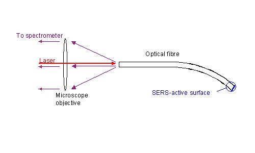
Figure 1. Experimental arrangement for a single-fibre SERS sensor.
Experimental
Instrumentation
Raman and SERS spectra reported here were measured using a 0.5 m triple monochromator with subtractive dispersion of the two first stages (DILOR XY) equipped with a nitrogen-cooled CCD detector (Wright Instruments) with a 298 x 1152 chip (EEV 88131) and a confocal laser microscope (Olympus BX40). The dispersion of the spectrometer is 1.1 nm/mm. A cw Ti:sapphire laser (Coherent 890) pumped by an Ar+ laser (Spectra-Physics 2000) serves as the excitation source. The Ti:sapphire laser emits at a wavelength of 702 nm. The laser radiation is filtered by a laser filter monochromator (Spectrolab, Labspec III) to remove low-intensity sidebands and the broadband spontaneous emission. Laser light with a power of 5.5 mW is focused by a microscope objective (Olympus, MPlan 10x/0.25) onto the uncoated end of the fibres and thus coupled into the fibre core. In this way, the SERS-active tip is illuminated through the fibre and the scattered light is detected through the microscope after passing down the same fibre (Figure. 1). The same objective and further lenses produce a twelve-fold enlarged intermediate image of the end of the fibre at the entrance slit of the spectrometer. The slit width is 300mm. Integration times are 10 seconds with 5 accumulations, unless otherwise stated.
Hard polymer-clad silica fibres (SpecTran, HCP-M0200T-06) with a core diameter of 200mm and a numerical aperture of 0.37 are used for most experiments. Home-made sample holders are used to position the fibres under the microscope and to place them in the vacuum chamber.
Preparation of fibre tips
Fused silica fibres are cleaved into 7 cm long sections. After removing the protective buffer coating of the fibres, this can be done either with a commercially available tool or manually by scratching and bending [17]. The SERS-active surfaces are then prepared on the freshly cleaved tips using the different techniques described below in Figure 2.
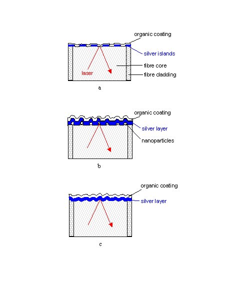
Figure 2. Structures of thiophenol-coated tips of single-fibre SERS sensors prepared by
a) slow evaporation of an island film on a smooth surface (AgIF),
b) coating with nanoparticles and silver (AgFON) ,
or c) evaporation of silver on a sandblasted (AgFOS) or abrasively roughened (AgFOAR) surfaces.
Silver island films (AgIF)
Fibre sections are positioned in a vacuum chamber, 50 cm away from a thermal evaporation source containing silver (Figure 3). The fibres are orientated in such a way that one end faces the evaporation source, whereas the opposite end is in the shadow of the fibre holder. The ceiling of the chamber with the attached fibre holder is rotated around its vertical axis during the evaporation process. 5 nm of silver are evaporated at a rate of 0.006 nm/s at a pressure below 10-3 Pa.

Figure 3. Scheme of the vacuum chamber for the evaporation of metal films on fibre tips.
Silver films over nanoparticles (AgFON)
Fibre tips are dip-coated with alumina particles in a 5% aqueous suspension of alumina and allowed to dry in the air. The agglomerate-free alumina (SEPP03, Fa. Piepelow & Brand, Germany) has a grain size of 300 nm. Further details are given elsewhere [9]. The dried tips are positioned in the vacuum chamber as described above. An adhesion layer of 2 nm of chromium is evaporated at a rate of 0.03 nm/s followed by the evaporation of 75 nm of silver at a rate of 0.2 nm/s. Figure 4 shows AgFON fibre tip produced in this way with a smoothly cleaved surface, a uniform particle coverage and a wedge that is typical for manually cleaved fibres. Such wedges are prevented by using commercial cleaving tools. However, these wedges usually do not disturb the performance of the sensor as they are often just protrusions of badly cleaved cladding material.
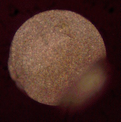
Figure 4. Image of the end-face of a 200 m m silica fibre after manual cleaving and coating with a AgFON surface.
Silver films on roughened fibre tips
The fibre tips are roughened either by grinding or sandblasting. To grind them the fibres tips are abrasively roughened on a conventional polishing machine with polishing papers of 30mm grain size. Finer polishing has been shown to lead to lower levels of SERS enhancement [15]. Sandblasted fibre tips are prepared by positioning cleaved fibres in a blast of silicon-based sand with mean diameters of 135mm at a pressure of 4 bar for five seconds. Both types of roughened fibre tips are rinsed with water and cleaned ultrasonically in acetone. Layers of 2 nm of chromium and 75 nm of silver are deposited on the roughened tips as described before, thus yielding silver films over abrasively roughened (AgFOAR) or sandblasted (AgFOS) surfaces.
Adsorption of the reference chemical
Thiophenol is used as a reference chemical to test the SERS activity because it forms chemically bonded, stable monolayers on silver surfaces [20] and exhibits a comparatively large Raman cross section in the spectral region used here. The silver-coated fibre tips were immersed in a 10 mM solution of thiophenol (>99%, Aldrich) in ethanol for 10 minutes and subsequently rinsed with ethanol.
Results and Discussion
SERS spectra of fibre sensors
Spectra measured through single-fibre sensors consist of the SERS spectrum from the tip superimposed on the Raman spectrum of the fibre core material (Fig. 5). The Raman spectrum of the fibre core material, fused silica, shows broad bands below 1100 cm-1 with the highest intensities below 600 cm-1. The test substance thiophenol shows three strong SERS bands between 1000 cm-1and 1100 cm-1 and other strong bands at 417 cm-1, 685 cm-1, and 1575 cm-1.
Measured through the fibres, the thiophenol SERS bands are weaker than the most intense silica bands (Fig. 5, spectrum b). Fortunately, the silica background is relatively low in the higher frequency range, so that the thiophenol bands above 600 cm-1 remain clearly visible. Even the SERS band at 417 cm-1 is clearly distinguishable from the intense silica background, because the silica bands with half widths above 23 cm-1 are broad compared to the narrower thiophenol bands with half widths below 15 cm-1. Therefore, the silica background can easily be subtracted from the spectrum of thiophenol measured through the fibre, rendering the pure thiophenol SERS spectrum (Fig. 5, spectrum c).
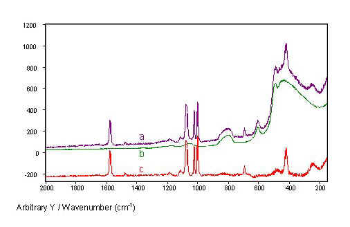
Figure 5. SERS spectra of thiophenol from an island film coated fibre tip recorded throughout the fibre
(a). The Raman spectrum of a fused silica fibre
(b) and the difference of both spectra
(c) are given for comparison. The spectra were normalized with respect to laser power and fibre length.
In contrast to the other types of fibre tip coatings, the island films are nearly transparent. Therefore, SERS intensities of substances adsorbed onto the tip itself can be compared with Raman intensities from substances in front of the tip. For instance, for thiophenol coated island film tips immersed in ethanol, spectra of both substances are superimposed. As a consequence, the quality of the SERS-active layer can be evaluated using intensity ratios of SERS and Raman bands, because both intensities depend similarly on laser power and coupling to the fibre.
The fused silica fibres can also be applied to Raman and SERS spectroscopy of a broad variety of organic substances, since the fibre Raman background is low in the so-called fingerprint region between 600 cm-1 and 1200 cm-1 generally used for analysis of organic compounds.
The intensity of the silica background increases with the fibre length [21] and determines the total measured intensity for longer fibre sensors. The shot noise of the spectrum increases with this total intensity [22]. Therefore, tips with maximum SERS enhancements are required when constructing long SERS sensors with reasonable signal-to-noise ratios.
Comparison of SERS enhancements
All four different preparation techniques render SERS-active fibre tips with considerable enhancement (Fig. 6). Spectra of thiophenol adsorbed at the fibre tips can easily be recorded through the fibre in all four cases, whereas no Raman scattered light can be detected from continuous smooth silver films at fibre tips. The thiophenol spectra recorded through the fibres only show bands of thiophenol and no bands related to the surface structure, i.e. the nanoparticles do not contribute any characteristic bands to the spectra obtained from AgFON tips. As expected, the intensities of the silica bands are comparable for fibres with differently prepared tips.
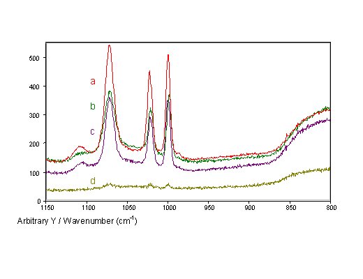
Figure 6. SERS spectra of thiophenol recorded through single-fibre SERS-sensors with different tip preparations:
a) AgFON,
b) AgIF,
c) AgFOS, and
d) AgFOAR prepared with 30mm grain size polishing paper.
AgFOAR tips show lower SERS intensities than the otherwise prepared tips. The other three types of fibre tips produced similar SERS intensities with slightly higher intensities than for the AgFON tips. For similarly prepared glass slides, the intensities for AgFON surfaces are approximately four times stronger than for island films. However, this ratio is not so large for fibre sensors, because in fibre sensors the SERS surfaces are reverse-side excited, a geometry favourable for island films.
On glass slides, island films showed about 2.4 times larger SERS intensities in reverse-side excitation than in front-side geometry. The intensities from AgFON and sandblasted substrates were comparable for reverse- and front-side measurements. Enhanced SERS intensities for reverse-side excitation of SERS substrates were earlier observed for slides with various SERS-active surface and organic coatings [23, 24]. In island films and AgFONs, the light can penetrate the thin silver layers on the fibre tips, making reverse-side excitation of SERS substrates possible.
It should be noticed, that the results from glass slides can not simply be compared with those from fibre tip surfaces. The characteristics of the fibre tip may also influence the formation of SERS-active structures. For instance, the mobility of silver atoms and thus the formation of island films as well as the adhesion of nanoparticles are likely to be different on freshly cleaved fused silica surface and on glass surfaces obtained in glass melt processing.
The AgFOAR tips yielded considerably smaller SERS intensities than the AgFOS and other tips in the tip geometry described above. Probably, the coarse polishing employed for the preparation of AgFOAR tips yields surface structures that are more shallow and less edgy than those produced with other preparation methods. Apparently, these polishing structures are less efficient as SERS enhancers. Nevertheless, the AgFOAR technique should not be discarded. Recent experiments have shown, that the SERS intensities from AgFOAR tips can be enhanced considerably by optimising the fibre tip geometry [25].
Summarised, concerning SERS enhancement, all four preparation methods are principal suitable for producing SERS sensors. Therefore, other aspects must also be considered when choosing the preparation technique for the sensors. Such considerations are, for example, reproducibility, robustness and reusability.
Reproducibility of sensor preparations
Due to their preparation, AgIF fibre tips have more homogeneous surfaces than those prepared by other means. This in turn leads to smaller variations of SERS intensities, when scanning AgIF tips under the Raman microscope. During measurements through the fibre sensors, the whole tip surface is, however, measured simultaneously thus averaging the enhancement across the surface.
Within the same batch of fibre sensors, the SERS intensities measured through the fibres from island film coated tips show standard deviations of 20%. This is only about a half of the deviations obtained for AgFON (42%) and AgFOS tips (38%). These standard deviations are somewhat smaller than those obtained from SERS microscopy at similarly prepared glass slides [because of the averaging effect mentioned above].
Thanks to the smaller standard deviations in SERS intensities from AgIF tips compared to those from the others investigated, this method of generating island films on fibre tips has the potential to enable us to manufacture sensors with better reproducibility than the other methods described here. However, the formation of island films depends crucially on metal evaporation rates and the cleanness of the fibre tip surface. Instabilities in the evaporation rates or contamination of the surfaces may result in a considerable reduction of the SERS enhancement. As a contrast to island film coated fibre tips, different batches of alumina coated ones tend to give more similar SERS intensities because the preparation parameters and especially the evaporation rate, are not as critical for the formation of the structures involved.
Robustness of SERS sensors
A drawback with AgIF fibre tips is their limited robustness: Even the slightest touch can damage the island films, and chemicals can easily penetrate the glass / island interface and thus remove some or all of the islands from the surface.
The thicker silver films that are used for AgFON coatings can exhibit stronger adhesion because it is possible to deposit an underlying adhesion layer, for example 2 nm of chromium. Such a layer cannot be applied with AgIF, because it would reduce the mobility of silver atoms at the surface and thus hinder the formation of islands. Therefore, AgIF tips are more sensitive to mechanical strain and chemical attack than AgFON tips. However, AgFON tips can easily be scratched as the nanoparticles themselves do not stick tightly to the surface.
The AgFOAR and AgFOS fibre tips are more robust than the others for two reasons: firstly, a continuous silver layer covers the tips completely with a strong adhesion due to the thin underlying chromium layer. Secondly, the rough sub-structure has been engraved into the fibre’s silica core. This provides a further advantage the fibre tips can be regenerated after use simply by dissolving the silver layer and by re-coating the structured tip surface again with a new silver layer.
Conclusions
Without any cleaning procedures, SERS-active surfaces can be prepared on freshly cut tips of optical fibres by slow evaporation of metals forming island films, by evaporation of metal films on deposited nanoparticles, and by evaporation of metal films on abrasively roughened or sandblasted tip surfaces. Since all investigated preparation methods result in similar SERS enhancements, other criteria such as mechanical stability or reproducibility must be considered when choosing the most useful method of sensor preparation. The AgFOAR and AgFOS methods give promise that these may provide the highest durability of the coating structure and easy regeneration of used tips.
Acknowledgements
This investigation is financially supported by the Bundesministerium für Bildung, Wissenschaft, Forschung und Technologie (grant 13N6886). The authors thank Prof. Dr. E. Voges and M. Kahl, Lehrstuhl für Hochfrequenztechnik of the University of Dortmund, for their interest and support.
References
- G.E. Walrafen and J. Stone, Appl. Spectrosc. 26, 585 (1972).
- H. Yamada and Y. Yamamoto, J. Raman Spectrosc. 9, 401 (1980).
- R.L. McCreery, M. Fleischmann, and P. Hendra, Anal. Chem. 55, 146 (1983).
- S.D. Schwab and R.L. McCreery, Anal. Chem. 56, 2199 (1984).
- P.J. Hendra, G. Ellis, and D.J. Cutler, J. Raman Spectrosc. 19, 413 (1988).
- C.G. Zimba and J.F. Rabolt, Appl. Spectrosc. 45, 162 (1991).
- M. Moskovits, Rev. Mod. Phys. 57, 783 (1985).
- S. Nie and S.R. Emory, Science 275, 1102 (1997).
- W. Hill, B. Wehling, C.G. Gibbs, C.D. Gutsche, and D. Klockow, Anal. Chem. 67, 3187 (1995).
- B. Wehling, W. Hill, and D. Klockow, Intern. J. Environ. Anal. Chem. 73, 223 (1999).
- W. Hill, V. Fallourd, and D. Klockow, J. Phys. Chem. B 103, 4707 (1999).
- S.D. Schwab, R.L. McCreery, and F.T. Gamble, Anal. Chem. 58, 2486 (1986).
- M.L. Myrick and S.M. Angel, Appl. Spectrosc. 44, 565 (1990).
- J.M. Bello, V.A. Narayanan, D.L. Stokes, and T. Vo-Dinh, Anal. Chem. 62, 2437 (1990).
- K.I. Mullen and K.T. Carron, Anal. Chem. 63, 2196 (1991).
- K.I. Mullen, D. Wang, L.G. Crane, and K.T. Carron, Anal. Chem. 64, 930 (1992).
- C. Viets and W. Hill, Sens. Actuators B 51, 92 (1998).
- H.L. MacDonald, R.C. Jorgeson, C.L. Schoen, B.F. Smith, S.S. Yee and K.I. Mullen, Proc. Int. Soc. Photo-Optical Instrum. Eng. (SPIE) 2293, 198 (1994).
- D.L. Stokes, J.P. Alarie, and T. Vo-Dinh, Proc. Int. Soc. Photo-Optical Instrum. Eng. (SPIE) 2504, 552 (1995).
- C.J. Sandroff and D.R.J. Herschbach, J. Phys. Chem. 86, 3277 (1982). 21. J. Ma and Y.-S. Li, Appl. Opt. 35, 2527 (1996).
- W. Hill and D. Rogalla, Anal. Chem. 64, 2575 (1992).
- C. Jennings, R. Aroca, A. Hor, and R.O. Loufty, Anal. Chem. 56, 2033 (1984).
- J.M. Bello, D.L. Stokes, and T. Vo-Dinh, Anal. Chem. 61, 1779 (1989).
- C. Viets and W. Hill, J. Raman Spectrosc. 31, in press (2000).
REF: C. Viets and W. Hill, Int. J. Vib. Spect., [www.irdg.org/ijvs] 4, 2, 8 (2000)