Sampling in FT-Raman Spectroscopy, High and Low Temperatures (Why Bother to Cool?)
![]()
Patrick J. Hendra
Should one wish to follow a reaction or physical change which occurs at low temperatures there is little alternative to cooling. P.T.F.E. is highly but not exclusively crystalline and the crystals contain -CF2CF2-CF2– species in helical structures. Below 19°C the helix has a different pitch from that at high temperatures and the spectrum changes as the crystal structure alters. Or – you might wish to run the spectrum of a solid melting below room temperature – cool, freeze and study. Raise the temperature and follow phase changes below the melting point, raise the temperature and melt the specimen. All this is pretty obvious stuff but students of Edition I will ask – what about sample heating? The laser itself will raise the temperature by a variable amount but certainly not by a trivial degree or so; the problem can be far more serious than that. Sometimes, sample heating can be a disaster. If a transition of interest occurs near room temperature, the bulk of the specimen can easily lie below the critical temperature but the tiny volume illuminated by the laser can be far hotter and in fact ABOVE the crucial value. I suggested ways of solving this problem in Edition I but in many cases there is no alternative to cooling. Let us say a transition of interest (freezing/melting or a crystal structure change) occurs at 10°C and laser heating might amount to 40-50°C; the precise value we know not. In this type of case, cooling to cryogenic temperatures will guarantee that no harm is done by the laser. So we need a cold cell.
Cold Cells
In principle there are four types of cold cell suitable for Raman spectroscopy:
- Peltier Cooled Cells
- Cold Finger Cells
- Transfer Gas Cells
Peltier Cooled Cells
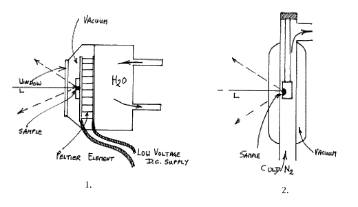
The principle here is that a large capacity Peltier device is set up to cool the specimen. Peltier Coolers are flat plate devices that establish about 40°C between their hot and cold surfaces. For our purpose, the thickness of the device is about 4mm and its area 900mm2. The trick is to really adequately cool the hot surface, prevent heat leakage from the hot to the cold surfaces and yet cool a sample of reasonable size. As it turns out, to prevent heat loss and frosting, the cell has to be evacuated and the hot surface cooled with water. Raman cells are always as compact as possible and FT ones are particularly so, thus the Peltier setup is rather clumsy. A commercial cell based on this principle has been offered but the need to supply water cooling, high currents and vacuum inside the sample area makes the cell very unattractive to the user. The principles and characteristics are shown below:Typically you need 6 or so amps at a low voltage so the cells are safe to use, but I have found that the minimum temperature achievable is unimpressive at ~ -20°C. The problem is to really efficiently cool the hot surface. The cells are clumsy and hard to fill and empty. As a result, this type of cell has not proved to be a great success.
Cold Gas Cells
An alternative approach is to use a very cold stream of gas derived from boiling a liquid refrigerant. By far the most popular is “liquid nitrogen blow-off”
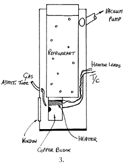
I suppose all of us are familiar with the principle – Dewar of liquid nitrogen with a heater dangling in the liquid. Apply a current – generate a steady rapid stream of nitrogen at a temperature near its boiling point and duct this to the experimental area. The problem is that a relatively large volume of gas is needed because its heat capacity is very low. Hence, a low temperature compatible tube has to pass from the Dewar, through the light trap, and into the sample chamber. This can be achieved but the tubes tend to be stiff and hence there are problems with sample alignment and geometry. The cell itself is usually made of glass and is in fact a cylindrical Dewar vessel. A schematic diagram is given below. Brucker offer a cell of this type for their FT-Raman instrument.
Cold Finger Cells
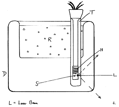
In many respects these are the standard, the most versatile and the best cells of all. The principle is the one adopted in infrared cold cells, a vertical tube full of refrigerant carries a sample holder at its bottom. The space around the holder and the refrigerant container is evacuated. These cells are usually made of metal but glass is fine. A schematic is given below:
Appropriately engineered, liquid helium temperatures are readily accessible with these devices. A sample in any condensed phase can be mounted in the holder and cooled and/or its temperature controlled by compensating for the cooling by heating electrically. Alternatively, gases can be introduced and condensed onto the ‘cold finger’ surface, enabling owners to study matrix isolated species. Several gases can be introduced, condensed and allowed to react.
The only problem with these cells is that they tend to be bulky, need continuous pumping and if gas admission is planned, the services can be bulky and complex. As a result most systems are mounted on a moveable trolley and rolled up to the infrared or Raman instrument as required, i.e. they usually operate with the sample chamber open. This is fine in a sophisticated research environment but quite inappropriate in analysis or where an FT-Raman instrument is housed with other instruments in an open laboratory.
Transfer Gas Cells
Our choice at Southampton is this type of cell. The operating principle is not completely obvious, so I draw a schematic below:
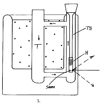
The device consists of a peculiarly misshapen Dewar (D) made of glass, containing a tube (T) open to the atmosphere, offset from the centre. Liquid refrigerant (R) in the bowl of the Dewar cools the surfaces of tube T and hence generates a downward flowing film of gas close to its inner surface. This cold gas flows to the bottom of tube T and then rises up its centre, to circulate again (and again). If a sample (S) is suspended down the centre of the tube it is, of course, exposed to this circulating gas and cooled. The sample ‘probes’ are of two types – plain ones containing a thermocouple and fitted with a black anodised aluminium sample holder or electrically heated ones. In this latter type, the sample holder carries a small heater H (6 watts is fine), enabling the user to heat the sample to a controlled value above that of the refrigerant. In deep cells, e.g. those used in conventional Raman spectrometers, the cooling can be so effective that using liquid nitrogen and exposing the centre tube to laboratory air, liquid oxygen will condense at the bottom and sit there quietly below its boiling point. In FT instruments the sample chambers tend to be rather lacking in head height and as a result the cooling is less effective. Using liquid N2 a typical cell will easily reach -150°C. Electrical warming can achieve controlled temperatures up to -80°C with a stability of around ±1°C. To achieve monitoring and good quality control, we invariably use a very sophisticated differential proportional controller (CAL Model 3200[1]) and a copper constantan thermocouple (Type T). Stabilized D.C. heating is better than transformed A.C. as by this means interference with the instrument electronics is eliminated.
If heating exceeds 70 or so degrees, the rate of nitrogen boil off becomes excessive, so the time has come to change refrigerant. Using a combination of liquid N2, Acetone/solid CO2 and ice and salt, the whole temperature domain from -150°C -> room temperature is accurately accessible.
This type of cell relies on the heat transfer efficiency of the gas inside tube T. In turn, if laboratory air is used, a ring of ice and solid CO2 will form if liquid N2 is the refrigerant, but if undisturbed this poses no problem. What of other gases? Helium has a far greater heat conductivity coefficient than air, so its use is obvious. On the other hand, the density difference from cooling is less because of the fundamentally lower density of helium than of air[2].
We have experimented with a tiny bleed of helium into our transfer gas cells but noticed very little effect.
Scientists being scientists, we could not leave a good idea alone and came up with the design below. The cell made in borosilicate glass is a triumph of the glassblowers art and was made by Mr. Mike Catlin about 18 months ago in the Department.
The cold gas falls down tube T, is forced up TS and hence circulates rapidly round and round the glass loop. The sample hangs as it does in our normal cells, but this time down tube TS. The Sample point is marked in the diagram. Cooling is so effective in this cell that a metal shutter is fitted inside tube T to restrict flow when the sample is heated. (The shutter is not shown in the diagram)
One point about glass: we find that individual pieces of borosilicate glass can be far more fluorescent in the n.i.r. than others. The worst can be more than 100x more fluorescent than the best! Careful selection is therefore essential.
Transfer gas cells only enable you to cool a sample. You cannot evacuate or expose the sample to a reactive gas, hence they look at first sight much less attractive to users than the cold finger devices. There is no doubt that this design is relatively lacking in versatility but it makes up for this failing in convenience. Once located in the instrument, samples can be changed in seconds. There is no vacuum to break and no precautions are needed to prevent frosting. As they are removed from the cell, probes are instantly frosted, but this is not a problem when one introduces a specimen.
In some experiments relatively large samples are encountered, e.g. silicon or germanium wafers. In principle tube T can be made large and hence these can be examined. The only problem with enlarging the tube is that the sample point then falls a considerable distance behind the front glass surface and the collection optics may not then have adequate characteristics. In some FT instruments, space around the sample is at a premium, e.g. the Nicolet machines. In these cases, transfer gas cells can be devised but they need to be of small diameter in the plane of the sample, widening out above the optics, to hold a reasonable volume of refrigerant. Where space is restricted it can be very hard to devise alternatives to the transfer gas designs.
[1] Controls & Automation Ltd.
[2] Using PV=nRT the density of a gas doubles if cooled from room temperature to -120°C.
Heated Cells
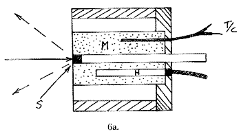
Just as one may wish to cool, heating can be required. Hot cells are far simpler to build than their cold counterparts, since metal is perfectly satisfactory and no vacuum jackets are required. In these cells a solid sample S is compressed into a cylindrical space with a piston P behind it. The surrounding metal block M is heated by a small heater H and monitored with a thermocouple T/C. The heated block is supported and surrounded by an insulator.
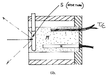
A liquid sample equivalent carries laboratory ampoules, sample vials, NMR tubes or melting point tubes and is shown below:
When one heats a sample it, and the surrounding metal, radiate as they act as a black body source.
The wavelength at which this radiation is maximised is given by Stefan’s law.
Further, the intensity rises dramatically as temperature is increased.
As a consequence, there will be a temperature domain in which samples begin to emit within the spectral bandwidth of our Raman experiment. Exciting with NdYAG lasers lays this between 1 and 1.7μ and at temperatures above 150°a background always appears, due to black body emission. Careful design to minimise pickup from the heated parts of the cell can help, but it is very hard to record spectra much above 180°C with an FT instrument. The background above this temperature becomes overwhelming at high shifts. In principle, one could operate above this temperature by subtracting the background, but there are two problems with this idea.
Firstly, as the temperature is increased there will come a situation at which the centre burst, due to the total scatter (Raman plus background), will saturate the detector pre-amplifier. Secondly, the noise in an FT instrument is spread over the whole spectrum, hence the shot noise from the background makes the spectrum worse and worse as the sample is heated, even well away from the emission maximum.
There are several tricks one can do to help. Assuming one is willing to restrict the spectral range to, say 0 -> 1500cm-1 shift, a filter can be incorporated cutting out to the red of, say, 1.35μ. As a result, the detector sees no background until more than 200°C is reached, and saturation and noise problems are not encountered until the sample reaches nearly 300°C. Obviously this ruse is fine but very restricting. An alternative has appeared in the literature due to Bob Bennett of Renishaw, and involves a clever exploitation of the properties of the Fourier Transform Process.
Using a commercial FT Raman system based on the NdYAG laser, the interferogram appears at the detector as an audio frequency signal. To explain, the interferogram has appearance –
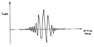
As the optical delay is scanned, the detector sees the waveform as an AC signal. The speed of scan is such that the signal happens to fall in the audio domain.
Bennett heavily modulates the laser at 530hz, hence the component of the interferogram due to the Raman signal mixes with this modulation frequency to produce three superimposed interferograms – one over the normal frequency domain and two others up and down shifted by 530hz respectively. The FT processor now does its deed and generates three spectra, a conventional one and two others shifted by the spectroscopic equivalent of the laser modulation frequency. As a consequence, Bennett sees the spectra shown in the figure below –
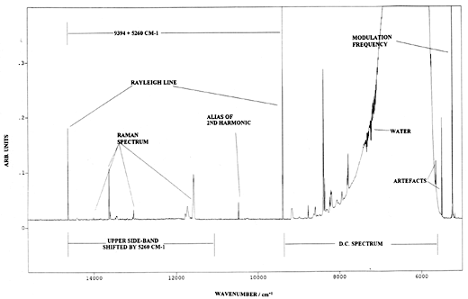
| Output from a Raman spectrometer operating under Bennetts’ experimental protocol. Instrument P-E2000R F-T Raman spectrometer. Laser modulated at 526Hz. Resolution 8cm-1. Note frequency scale is absolute and the spectrum occurs nominally to the blue side of the conventional one. D C Spectrum – conventional output of heated polystyrene sample. Upper Side bond spectrum – modulated spectrum clear of black body emmission. |
From R.Bennett Spectrochim. Acta 50A 1813 (1994)
Note: the normal spectrum contains the thermal emission background but of course the shifted (or modulated) spectra do not, because only the Raman spectrum is modulated by the periodically varying laser output. My view, for what it is worth, is that this experiment could prove to be of immense importance, since it describes a pioneering effort where modulation and Fourier Transformation can be exploited in FT-Raman. The NMR people routinely exploit these procedures with very considerable effect. I suspect vibrational spectroscopists will eventually do much the same.
Accessory Suppliers
In FTIR there is now an industry-wide standard for holding, illuminating and viewing samples, and as a result major accessory manufacturers offer a wide range of cells, reflection devices, ATR systems etc. which are fairly universal – they can be made to fit all, or almost all, of the commercial FTIR machines. This is not so in FT-Raman because each manufacturer uses a different sample holding system. They even have a range of collection systems – mirrors or lenses – so it is not possible to devise a cell suitable for a range of spectrometers. All the manufacturers offer accessories, some offer cold cells, hot cells, and others too are frequently developed for them by specialist suppliers.
This is a ‘niche market’ and the local office of your instrument manufacturer may have no details, but the headquarters people definitely will. If you have any difficulties, I am very happy to help – just ijvs [at] soton.ac.uk (e-mail us) .
REF: Int. J. Vib. Spect., [www.irdg.org/ijvs] 1, 2, 6 (1996)
